Viewers

I live in a house that is easily more than 100 years old. Living here has taught me that the term ‘this ole house’ is the basis of conversation with the repairman I called last week, rather than a syndicated production. By the generosity of God, I grew up on a farm learning to do all that you can to save paying others to do what you might accomplish. Life has taught me that you are a much better person if you mow your own yard rather than get a job, that pays enough money, that after taxes, you can still afford to hire someone else, to mow it for you, and pay for their weekly service, while you also pay a monthly fee to go to the gym or health club, in order to have a place to exercise.

Think about it……..Bob

Monday, May 5, 2014

Shaving Horse Plans, Diagrams, and Photos


Since the first time I saw a “shaving horse” I have wanted one.  Although it is somewhat specialized in its use, there is nothing better for the work that it allows you to do to wood.  I could even see this device a very helpful tool if you are into macramé.  You could use it to hold tight the woven area and allow you to work about 12 to 20 inches at a time before you shift and continue.

Here is my finished horse.  I have always called it a “draw horse” since the common tool is a “draw knife”.


Every year, I find that spring will sprout anywhere from 20 to 50 sapling trees in my back yard.  Most of them are either oak or pecan.  So I let some grow in the event I lose a large tree and want to replace it.  Once the young tree is about 12 feet high I will decide to let it grow or make a nice walking stick.  Here is one use for my horse…the ability to remove the outer bark in about one tenth the time it takes with a hand knife, and I can also shave the places where the branches were attached at the same time.

Also I like to save some of the winter storm branches that break off, and cut the good ones for legs when I make stools for sitting.  For this I leave the bark on the wood, but I need to form a nice round end on the wood about 2 inches long and 1 inch diameter to insert into the seat.  In the past I have stood at my bench belt sander for hours shaping the ends, and getting covered in the saw dust.  The horse is perfect for me to accomplish this task also.

I don't know anyone with a horse that I could go measure, so I got on the internet and Googled “shaving horse”.  I got many many photos and could pay to get plans, but I just do not like to pay for plans that I am likely to change a little anyway.  The photos that I liked were downloaded.  After I had a dozen or so, I started looking at each to find common features.  One was of a diagram that someone had drawn and added most measurements, with a short narrative.


This is the diagram I used as a reference while working on this project for basic measures.  I needed to realize that I was not going to have one that used a wide slab of wood 3 or 4 inches thick, so I focused on designs using boards 2 inches thick (actually 1 ½“).  Throughout all of this posting, if you see an angle used it will be 10 degrees or its compliment of 80 degrees.  All glue is Gorilla glue since this horse may be outside from time to time, and possibly get wet.

I started my project by finding two pieces of 2 x 6 at least 5 feet long.  From the two boards I found, I made sure one end of each was square, then measured 54” and drew a line on a 10 degree angle off my square to the other side (which made the other side about 1“ longer).  Now I have the two long pieces for the “bench” of my horse.  If the pieces cut off are at least 20” on the short side, then you can use one for the front leg.  It is also cut on an angle of 10 degrees on both ends such that the cuts are parallel.  Next I cut a short piece of the 2 x 6 to be 5 ½“ long for a spacer in the square end of the bench.

I put one of the long pieces on my work bench with the long side against me.  To this I put the front leg at the end with the slant and aligned the leg to be extended outward. 
 

The short piece, as a spacer, goes at the square end.


I put glue between the pieces, pre-drilled 4 holes with counter sink, and used 2 ½“ deck screws to bind them.  Then I put glue on the two pieces and added the other long board with 4 screws at each end.  I have learned to pre-drill holes for screws and counter sink for a clean non-split holding.

From a 2 x 4, I cut two pieces 20“ long with the same 10 degree slant on one end and the other end square.  From the square end, measure 5 “ down the leg and 1” from the shorter side, and place a dot.


Now at 10 degrees off the shorter edge, draw a line through the dot to the square end.  Measure 5 ½“ from the square end on the slanted line and mark.  Draw a perpendicular to this line from that mark to the closest edge.


This area I cut away on my band saw.  Next hold the leg against the rear of the horse in its position and with your pencil make an arc that will show where to cut the other corner away.


I rounded over the corner since it might tear my pants.  Use this leg as a template to mark the other leg.
 
On all three legs I chamfered the bottom to avoid any tear out when scooted across the floor.


I attached these two back legs using three 3“ screws in each with a deep counter sink where needed.


I took this assembly off the work bench and set it on the floor.


When I sat down on it, I knew some type of seat was needed.   From a 2 x 4, I cut a 6 ½“ piece and cut both corners out leaving a 1 ½” x 1 ½” tenon centered.  Using a 2 x 6 about 18” long I rounded the corners and routed the edges with a 3/8” round over bit.  A mortise 1 ½” x 1 ½” is needed to be centered with respects to the longest measure and located so the 2 x 4, when joined, will make the edge of the 2 x 4 flush with the edge of the 2 x 6.


After I had drawn the mortise, I drilled a 3/8” hole in each corner and used a jig saw to cut the mortise.


Then I spent about an hour with a rasp to fine fit the two pieces together.  The glue used even helped the tight fit to slide into position finally.  I love using mortise and tenon, but I’m not proficient enough to do it without a great deal of sanding and rasping till I am tired.

Seat the 2 x 4 piece down into the void of the bench and you have a movable seat to adjust as you feel.


If you get tired of the wood,  consider one of those square cushions for boats that seconds as a flotation  devise when you put your arm into the straps.  I know this is a ‘seat’, but this is a horse so I’ll call it the saddle.  My horse deserves respect.  So I’m in the saddle, straddled the 2 boards on their edge used for the bench… and I try to foresee the placement of the slot to cut in the “bridge“ to accept the vertical mid section, the “arm”, to be located.

I found  a 2 x 8, 34” board to use as the bridge and used it to determine some measures and placement.  This made me see I need to have the arm also, so I started on that part.  A piece of 2 x 6 cut to 30” is very strong.  As shown below, the ends become tenons, and shaped with a 10 degree angle.  This will add an angle for the “head” to meet the bridge with better alignment and afford a more comfortable position for the feet to apply pressure. 


Another variable in this equation is the measure of the head and the placement of its mortise so it will fit to the top of the arm.  Then you got to consider the placement of the ½” hole in the arm and the bridge for the rod that is like an axle in the design and allows the arm to move as I work.  At the bottom of the arm is the “treadle”.  Since it does have a 10 degree slant, all this wants to clear the floor and give the proper pressure for gripping the work.  Did I mention that the bridge is elevated on the working end and therefore we also have the height of the “riser” to consider.  So I needed all these parts in order to try to not make a mistake.

I  decided to make the treadle first because it is thinner than the piece for the head and they both need a mortise to accept the tenons located at each end of the arm.  A piece of 4 quarter cypress, 9” wide and cut to 10 inches worked here.  I made sure to run the grain parallel to the length of the horse for strength, but when I was rasping and fitting, I heard a crack.  To reinforce this I glued some strips to the bottom and across the grain.


The main time spent with this was after the mortise fitting was accomplished, it had to be modified to allow for the 10 degree slant.  To help me focus on the right areas, I placed a piece of masking tape about 3/16” from the short side of the mortise.  Then on the opposite side and the opposite end, place another piece of tape same distance.  This diagram should give you the idea:


Now the long task with my rasp to remove the wood that will allow the mortise to let the treadle rest in the 10 degree position.

With that accomplished I moved on to work on the head which will butt against the bridge to hold the piece that I will be attacking with the draw knife.  For this piece I used a 2 x 8 cut to 10 inches.  I drew the mortise to allow the head to fit on the tenon and cut it out on my jig saw.  Next the rasp to fit correctly, and then the final adjustment for the 10 degree slant.  After this was fitted, I cut a spruce 2 x 4 to attach to the underside of the head to increase the surface area for the pressure that the head will apply to the bridge.  No glue, just two screws through the back area of the 2 x 4 into the bottom of the head and placed cross grain to the head.  Then I cut off the sharp edges and shaped a 'bull nose' using my hand plane.


Spruce is a soft wood and will form somewhat to what it is holding.  Also if it should become gnarled, I can replace it easily.  Some examples show a leather facing added for friction.

Next I placed the treadle and the head on the arm snuggly,  and drew a line on each side of the tenons to reference the area for the dowel wedges that will lock the assemble together.  Mark the center of these lines on one side and with a 1/2" drill bit in my drill press, and the table tilted to 10 degrees,


I drilled through the tenon such that the outer diameter of the drill bit crosses the line about 1/8" on the top side and will exit the other side about 1/4" across the line.


With a 1/2" dowel, my 'home made' angle fence, and my table saw, I cut a 10 degree slice to the dowel.


After I checked the fit into the hole for the treadle, I marked the dowel for length and cut that part off.


The same process works for the dowel used to lock the head onto the arm.


Now I have the parts of the puzzle that will allow me to approximate the mortise in the bridge and the place to drill the hole in the bridge which is the pivot point for the arm.  Once I figured that out, I placed the bridge on my table saw.  I set the fence to be 2 13/16" from the blade.  I had marked the beginning and ending of the mortise on the bridge.  By raising the saw blade to the highest possible position, I could place two short pieces of tape on the fence at the points where the blade of the saw meets the table.


Now I lowered the table saw blade beneath the table and placed the bridge on the table saw against the fence.  With the saw running, I raised the blade slowly to allow it to cut through the bridge to the highest position for the blade.  Next the bridge was very slowly moved forward and backward until the marks on the bridge were aligned with the marks on the fence.  With this achieved, I turned the saw off, removed the bridge, and turned the bridge around but NOT to flip it over.  I want the same face up for both of these cuts.  Lower the blade, put the bridge against the fence, turn the saw on again, and make the second cut just as the first.  With a chisel I removed wood at each end of the mortise to complete the removal of that material not needed.


Once more I returned to the horse with the bridge, the arm, and some random pieces as risers.  With the arm inserted through the new mortise in the bridge and some pieces of different thickness I was able to determine the place of attachment for the bridge to the far end of the horse, and the location of the 1/2" hole for the iron rod through the bridge which supports the arm. 


To drill the hole through the bridge, I used a 1/2" bit that is about 12" long on my drill press in the horizontal position.  I think it would be almost impossible to use a regular length bit and drill each edge of the bridge hoping to have a path for the iron rod that will allow it to slide through.  I attached the bridge to the far end of the horse at the place I marked by using an old door hinge.


This will allow me to remove the pin should I ever wish to disassemble the unit in the future.  With the arm once again inserted in the bridge with the head and treadle attached, I used a large 1/4"  nail, like a spike, and slid it into the 1/2" hole in the bridge.  This allows me to position the arm with the bridge risen into a comfortable height and tap the nail so I make a final mark for the hole in the arm.  I removed the treadle, pulled the arm out of the bridge, and drilled the 1/2" hole in the arm on the drill press which insures perpendicular.

The 1/2" rod I got at Lowe's was 3 feet long.  I used the width of the 2 x 8 bridge plus about 1/4" extra on each end to allow it to have a washer and a pin, then cut it to length.  I inserted it into the bridge, put the washers on each end, and marked where to drill the 3/32" hold for the small cotter pins to be inserted.  Finally at my grinder, I beveled the ends so they would be slightly rounded.


The final part for my horse is the riser to the bridge.  The diagram I was referencing suggested a 7 1/2" riser, so I cut a 2 x 8 for a 7" length and a 2 x 4 to a 7" length.  On the 2 x 4 I removed a corner area 1 1/2" by 1 1/2".  Next the two pieces are attached with a couple of 3" screws by placing the notched end of the 2 x 4 to the edge of the 2 x 8 and centered.


This will allow the riser to be moved forward or back to make very minor adjustments to the height of the end of the bridge where I am working.  It also allows me to shorten the riser since it is not permanently attached.  This was good because I have already removed about 2 inches from the riser so that the bridge is not quite so high.

Another nice part of this design is that the rod that allows the arm to swing back and forth is located in the bridge rather than the bench.  This gives the operator the ease of adjusting the bridge up or down such that the work is adjusted to the person using the horse, without changing the position of the head to the bridge.  Also it will generate greater pressure by the head onto the material being worked, and minimizes the length of the mortise cut into the bridge.  The hole in the arm is located more toward the front edge and this results in the arm returning to the upright position when released, allowing the work piece to be moved without the operator having to pull the treadle with a foot movement.  The bench of the horse automatically provides a mortise for the arm, the movable riser, and the movable seat.

Already I think I might need another hole in the arm in order to adjust the distance between the head and the bridge, but I will wait until I have the need for that based on the thickness of the material I might be working with.


I sincerely hope this will help others make a horse of their own.

Thanks for viewing my blog......Bob

Materials (these are before cutting to exact measure) :

2 x 4 pine:  1 - 7" Riser support
                    1 - 6 1/2" Seat Support
                    2 - 22" Back Legs
      spruce:  1 - 8" Head (Bull Nose)

2 x 6 pine:  2 - 56" Bench
                    1 - 22" Front Leg
                    1 - 6" Back Spacer
                    1 - 30" Arm
                    1 - 18" Seat

2 x 8 pine:  1 - 34" Bridge
                    1 - 10" Head
                    1 - 7" Riser

4 quarter Cypress 9" wide & 10" long  (Treadle)

1/2" Iron rod (or Dowel) 8 1/2"  
1/2" Washers 2
Cotter Pins  2 - 1 1/4"
1/2" wooden dowel  24" (to lock head and treadle on arm)
1 door hinge 4"
Glue
2 1/2" & 3" deck screws


Saturday, August 3, 2013

Bird Feeder That Will Last


After making a second Bat House, I got a 16 ft., 4x4 treated post and placed this one so that it overlooked my driveway and parking area.  After attaching the Bat House and setting the post, I thought I was finished.  I went in the house, sat down in my recliner, and turned on the TV.  From this chair I have a window just to the right of the TV that I can see the trees outside and watch for squirrels.  When I looked out this time I was surprised to see that I had set this new post about 10 feet from the house but it was right in the middle of the window, and would obstruct my vision of the trees.  I was very disappointed, but not about to go back out and move the post.  So I did what some call "when life gives you lemons, just go make lemon aid".  In this case I pondered "what can I do to change this, because I hate where I placed that post".  After much thought I decided to mount a 1/2 in. dowel on the post so birds might land there and I would be able to observe their beauty.  Well that lasted about 2 weeks and finally I realized that the birds were not going to just flock to the roosting position without some type of incentive.

The best incentive would definitely be food.  So I decided to place a bird feeder on the post.  My younger daughter had been in a summer workshop and as a project, they made bird feeders.  I love the design and decided to use it as a model.  The only problem with the one she made was that it had a wooden piece that you would turn to the side to fill the seed.  After many years that 2 in. square piece of wood fell off and needed repair.  I also noticed that the wooden roof of that feeder was deteriorating from winter, summer, rain, and sun.  So I got out my aluminum roof flanging and made a top for the feeder with a sliding piece to allow the filling with seed.


This is what I wanted to copy for my new bird feeder, with some adjustments.  I wanted a larger capacity so I made it a bit wider.  I wanted a longer life, so I used barn cypress and a fully fitted metal top.  So after I took all the measurements of length, width, and angles, I started my new feeder. 

The first thing I did was to make a template for the sides with notes on it for angles, holes to drill, size, and other helpful information.


 Then I started on the bottom by cutting a piece  6 1/2" x 8".  Next I wanted the lip around this bottom to be about 1" tall and only 1/2" thick, so I cut enough stock to make these pieces.  I wanted the birds to be able to grip the top of this lip as they would a rounded branch, so I needed to round over the top.  To do this I made a jig for my band saw.


I took a piece of 2x4 to my table saw, tilted the blade to a 45 degree, adjusted the height, and made the first cut close to one edge.  Then I turned the piece around and adjusted the fence so as to complete the second cut and make the "V" that I wanted.  Next I used my band saw to cut out a rectangular opening where the blade will be positioned.  Now I clamped that to my band saw and positioned it so I could chamfer the corner edge on both sides of the top of the lip pieces.

 
Next I took those pieces to my bench top belt sander to round over the top.
Now I was ready to cut the ends to length with 45 degrees and glue them into place.

 
All glue used on this project is Gorilla Glue.  It is a polyurethane glue and will not deteriorate from rain water.
 
Next I cut the sides.  Each must be 5 1/2" wide and 8" tall, with the slope for the roof at 25 degrees.  After I ensured that the two were precisely the same dimensions, I set the miter gage for the table saw for 12 1/2 degrees.

I set the blade of the saw so that it would cut a depth of only 1/4".  Then very carefully I lined up the piece with the blade so it would be just inside of the top corner and cut a groove from top to bottom.


  I flipped the side around and aligned the corner with the blade again to make the cut for the other groove.  The same process applies for cutting the two grooves in the other side. 


Now the grooves are ready to accept the plastic rectangles and the sides are ready to attach to the bottom.


I carefully centered the sides on the 8" length of the bottom so that they are only 6 1/2" apart and marked the position, then glued the sides to the bottom.

 
Once the glue had set for about an hour, I used my countersink drill bit and predrilled holes for 2 - 2" decking screws on each side.


Next I cut two pieces of plastic 6 7/8"x 5 1/4" on my table saw.  These will slide down in the grooves on the inside of the sides.  Making sure that they will fit and not bind in the grooves, I placed one in and marked where the bottom of that plastic piece made contact with the top of the lip.


Then I took my mallet and a 1/2" chisel and notched the lip until the plastic would slide down low enough that the top was even with the top of the side where the groove held that piece of plastic.  I noticed that there was an opportunity for the seed to accumulate in the trench created by the rounded lip and the side piece, so I used the chisel to remove the wood between the two notches for the plastic.


This I made into a slope of about 30 degrees so the seed would track away from the side as the level dropped down and the feeder became empty of seed.


Then I placed a piece of wood on the top just to ensure that the top of the plastic would not be in conflict with the roof.  Now before I put the top on the feeder I must complete a few 'get ready' things.  From a wire coat hanger I cut two 10" sections that will be installed for the hanging harness.

 
Each of these have an end that will prevent them from pulling through.  I used my needle nose pliers and after gripping the wire perpendicular to the pliers, I wrapped the wire around the pliers so as to make a full circle.  Then I bent the wire perpendicular to that circle.


These wire pieces will go through holes near the peak of the roof and must be installed before the roof goes on the feeder.

Now I can cut the two pieces of 1/2" plywood for the roof.  These are 10" x 7" each.  The 10" run from side to side.  One of these will have the fill hole for seed.

 
This hole will be 1 1/4" x 1 1/4", centered from side to side and 1" from the top.  I drilled a 1/4" hole and used my Jig Saw to cut the square.


After I cut the square out, I realized that I needed to match this position in the metal top, so I added this to my template as a guide for later. 


Also I had to tilt my table saw blade about 32 degrees to trim the top edge of the roof.  This will make the two sides have the correct angle and prevent a gap across the top ridge.


Now I put glue on the top of the sides and attached the roof with two 1 5/8" decking screws.  Be sure to dry fit the roof pieces so that the ridge will be in the best alignment.  I also bent the two wires slightly just to prevent them from sliding back into the interior of the feeder.

I used a piece of aluminum roof flanging 20" wide to cut the piece for my top cover.  This piece should have a 1" extra boarder to allow the bending which is how it is attached to the feeder.  Final measure for my feeder was 16" long and 12" wide.  Using my awl, I marked lines 1" from the edge on all 4 edges.

 
Next on one of the 16" sides, I cut the corners with a tab to fold inside when the metal in fitted to the top.  Be sure that the tab is hinged on the 12" side.  This will make the tab fold so that it lays against the longer side and this will prevent the tab from causing you problems when you slide the feeder in and out of the folded sides while fitting and bending.


Now I can make 90 degree bends on one 12" side and the 16" side with the corners cut.  This will look like the start of a pan when it is finished.  Place the feeder, upside down, into this pan and snug it to the corner with the two raised edges.  Now carefully tilt the feeder onto the other area and ensure that the line is accurate for the folding of the other edge on that side.  It could be slightly over or under the original 1" mark and should be adjusted as needed so the top will fit as snuggly as possible.  I also marked the point at each end of the ridge so I know where to cut and bend for the ridge.  Next I remove the feeder and bend a 90 degree on the opposite 12" side.

 
I made an angled cut at the ridge mark so that when I bend the ridge, the edge will not cause problems.

 
I used a 1/2" piece of plywood to position in the corner so I could complete the second 90 degree bend on the part of the metal that wraps under the roof.  This I did on one of the 12" sides and half of the 16" side.  When this was completed,


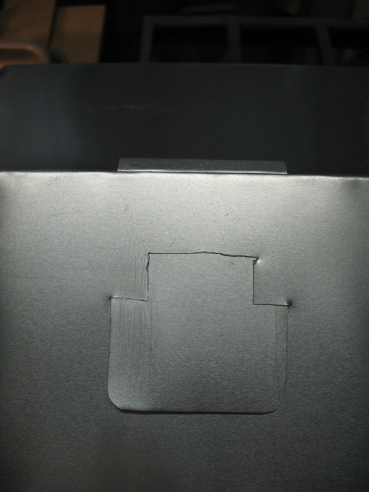
I once again placed the feeder upside down into the metal and checked the fit, as well as the markings for the ridge.  I removed the feeder and made the bend of about 50 degrees on the ridge line.  Now I placed the metal back on the feeder and checked the fit.  At this time, before the top is fully attached, I need to cut the square into the metal that will match the filler hole in the wood roof. 


This is when the template really helps.

 
After I mark the square, I use my DREMEL tool with a cutting disk.

Once I am satisfied with the metal and the fit, I am ready to complete the bending for the rest of the edges.  I placed the feeder in the metal upside down and worked around the other edges bending and tapping with my 90 degree edger (same one I used for the roof on the Bat Houses) and my mallet.  Also cutting the corners, ridge mark, and insuring a tight fit.


I cut 1/2" slits on each side of the filler square, and then I cut a piece of metal 2 1/4" by 4".  This will be the slide that covers the filler hole.  Once it is cut,


I round two of the corners, and I used some wide mouth wielding pliers to fold the top over about 3/8" onto itself twice as a handle.


Next I position the slide where it will be located and insure its position.  Then I marked the ridge at both sides of the slide


 for the slot that will allow the slide to be inserted.  This cut is made with my DREMEL tool.  Be sure that you favor the other side of the ridge for this slot.


Now the slide can be inserted into the slot and eased down until it makes contact with the two slots.  If the slide is difficult to mate with the slots, then you might use the wide mouth pliers and just very slightly bend the bottom of the slide upward.


Here you see the slide in harmony with the intended positioning.


At this point the feeder is finished, but I had to make it ready to be joined with the 4 x 4 post.  I cut two pieces of treated wood 3/4" x 1 1/2" about 12" long.  I used a piece of 4 x 4 post to mark where to drill 1/2" holes 1/4" deep.  Then I cut two pieces of 1/2" dowel rod about 4" long and two pieces of 1/2" PVC pipe 3 3/16" long.


I drilled through the ends of the 12" long pieces with a 5/32" bit and into the ends of the dowels, so I could put a 1" pan head screw with a small washer that will secure the ends of that assembly on both sides of the outer dowel.


Next I positioned the assembly to the bottom of the feeder to be sure that it is square and centered, and predrilled the holes for some 2" deck screws.


Now I must make a hanging assembly by first curling the ends of the wires that extend from the sides of the feeder,


and then attaching another wire curled in the middle and hooked on each end.


I predrilled and screwed a 3/8" hook into the post.  Then I found an old pulley and a long piece of 1/4" rope.  Once I attached and secured the feeder to the post, I needed to adjust the hanging device in order that the feeder would rest in a good horizontal position.


This required me to adjust the side closest to the post to be shorter than the other side.


I cut two pieces of 1" x 1" stock.  One was 6" and the other was 8".  This gave me a place to tie the other end of the rope and a take-up reel for when the feeder is raised to the maximum height.


As a last minute effort I made a 16" length from 1" x 1" stock and rounded the outer ends as a dowel for a perch stick for the birds.  This I mounted under the bottom of the feeder.


Now the bats and the birds will share the same post.  Bat house faces one direction and the bird feeder faces the other.


There have been no complaints from the birds, as of yet.

Good luck, Bob


A HELPFUL ADDITION:


 After I finished my feeder and once the birds got acclimated to it, I realized when I went out to fill the feeder the second time that there was no table or place, other than the ground, that I could put the bird seed that I was holding in my hands.  I could not even use my hands to let the rope out that allows the feeder to descend down to my level where I could fill it again.


I got this plastic filler from a garden center.  It is kind of like a funnel but has a sliding piece so you can fill it with seed and then once you put the small end into the filler hole, you pull the sliding piece and it allows the seed to fall down into the feeder.  My problem was that I had this full of seed and as you can see this can't be set down because it does not have a flat bottom. 


So I cut a piece of treated 1 x 6 board about 8 inches long, cut a square hole in one end, centered, about 2 inches from the end.  This I attached to the post with a couple of hinges.


Next I added another 1 in. piece across the end which will butt to the post and support the board when it is in the horizontal position.


I added an eyelet to the post, and a small hook on the board so this shelf can be raised and held in the vertical position when not needed.


When I lower this shelf, I can set the plastic filler and the extra coffee can, both full of bird seed, and my hands are free to lower the feeder.


Set the filler in the feeder, pull the plastic slide, and when this is empty I can pour the seed from the can into the filler to complete the filling of the feeder.

Hope you enjoy this and love watching the birds......


A few of the visitors to my feeder:


I even made one special for my neighbor:


Hope this gives you good ideas.....

Bob